RG830 Robot Manual
1. Emergency Stop
When the robot is powered on, the emergency buttons on the robot and other external emergency situations must be cleared, and then the Motor On button should be pressed.
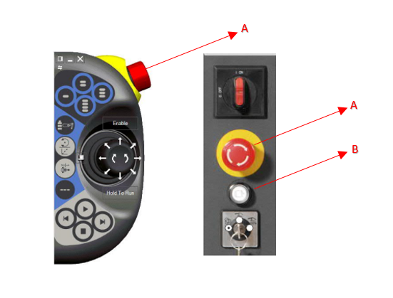
A: Emergency Button
B: Motor On Buttton
2. Working Modes

- A - Automatic Mode: Production Mode
- B - Manual Mode: Movement and controls can be performed in Jog modeog mode.
3. Robot Axis Control with Jog Movement
- When the robot is in manual mode, the 'Motor On' button on the right side of the FlexPendant must be pressed to activate the movement units.
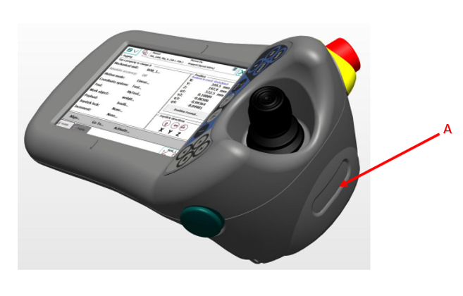
A: Motor On Button
- From the menu bar at the top left, you can enter the Jogging page and see the status of the axes.
- We can move axes 1-6 individually. On the first press, you can see the directions of axis controls between 1-3, and on the second press between 4-6 under the relevant axis number.
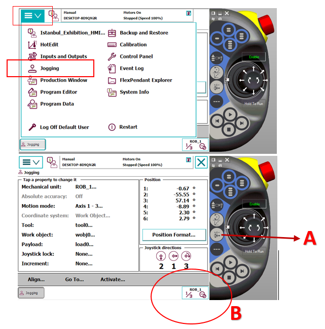
A: Axis control selection between 1-6
B: Currently selected axis range
- The robot can be moved linearly in X, Y, and Z axes. These movements are performed by referencing the Work Object (Wobj) selected in the interface, and the direction of movement is determined by the orientation of the relevant Wobj.
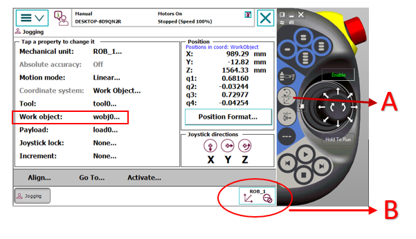
A: Linear and Orientation Movement Selection Button
B: Linear Movement Display Icon
- Orientation movement according to Tool selection.
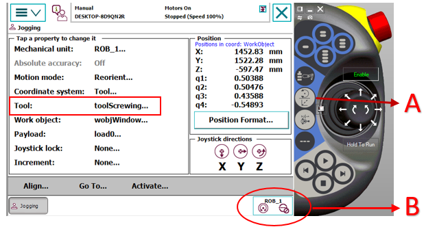
A: Linear and Orientation Movement Selection Button
B: Orientation Movement Display Icon
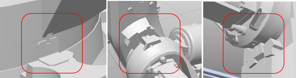
4. Robot Axis Calibration
- During the initial setup of the robot, a separate calibration process must be performed for each axis. During calibration, the zero reference marks (notches) for each axis should be aligned with high precision so that they match exactly. Each axis has its own notch.
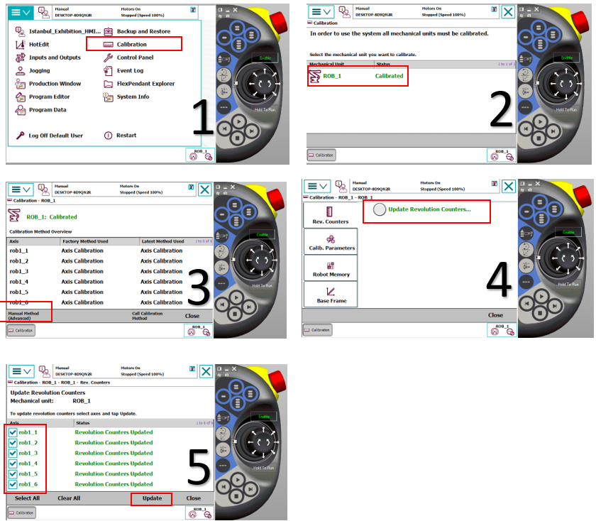
- After all axes on the robot are physically aligned with the calibration notches, you can follow the visual steps below to record the relevant values via FlexPendant. This process should be applied during the robot's initial setup or when a 'Robot calibration lost' warning is received from the system
5. TCP (Tool Center Point) Introduction
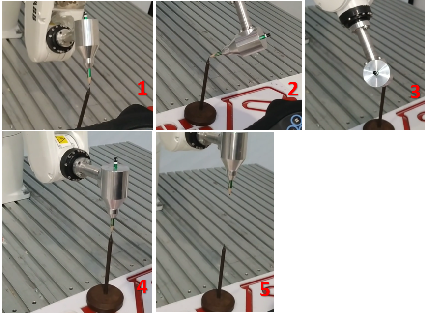
TCP (Tool Center Point) definition is performed by approaching a fixed, sharp-pointed reference point from different angles. The following steps must be followed to correctly define both the center point and the Z-axis direction:
- TCP & Z Approach Method
In this operation, a total of 5 approach points must be defined to provide high precision:
Approach 1, 2, and 3 (TCP Determination): The reference point is touched from three different directions with approximately 120° angles between them.
Approach 4 (Perpendicular View): The tool is brought into contact when positioned exactly perpendicular (90°) to the reference point. This is the basic reference point for orientation calculation.
Approach 5 (Z-direction Definition): The tool is introduced by lifting it upward from the reference point in the Z-axis direction. This final point ensures that the robot correctly perceives the positive Z-direction in the tool coordinate system.
- Critical Application Notes
Precision: All approaches must contact the apex (end point) of the fixed reference point with the same millimetric precision. Deviations in contact points directly reduce the robot's working precision.
Verification: After the definition is complete, the robot should be moved in manual mode (Orientation) to verify that the tool tip remains fixed at the reference point.
- Approach Visuals
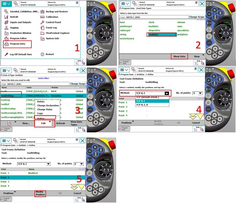
- Tool Introduction Calibration Steps
Follow the visual sequence above to provide precise approach to each reference point. When access to each point is completed, press the 'Modify Position' button specified in step 5 of the image below to record the relevant coordinate to the system. After all points to be defined are taught in this way, press the 'OK' button to complete the calibration process.
NOTE: The robot must be in Manual Mode for this operationoperation.
6. Wobj (Work Object) Introduction
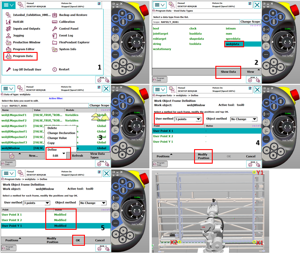
Wobj (Work Object): A user-defined coordinate system used to define parts or fixtures in the robot's work area. In ABB robot systems, the Wobj definition process is performed using the 3-Point Method on the relevant surface.
- Definition with 3-Point Method To create the coordinate system, the operator sequentially teaches these three reference points:
X1 (Origin Point): The starting (zero) point of the surface to be defined. The center of the coordinate system is considered to be this point.
X2 (X-axis Direction): The second point that determines the direction of the X-axis. The line between X1 and X2 creates the positive X-direction of the system.
Y1 (Y-axis Direction): The third point that determines the direction of the Y-axis. This point describes the positive Y-direction perpendicular to the X-axis.
You can teach the robot to each introduction point (X1, X2, Y1) separately and by clicking Modify Position as shown in figure 5, you can teach the coordinates of that point. After all teaching is complete, you can click Ok as shown in figure 5 to complete the operation.
Automatic Z-axis and Planarity
The plane created by these three points is mathematically calculated by the system to automatically determine the Z-axis.
Movement on Inclined Surfaces: Even if the defined surface is inclined, when the robot moves with the Wobj reference of this surface, it performs a perfect linear movement based on the surface's inclination.
Precision: The farther apart the X and Y points are and the more precisely they are selected, the higher the accuracy of the created Wobj.
NOTE-1: The accuracy of the TCP values of the Tool used during the Wobj definition process directly affects the precision of the created work object.
NOTE-2: The robot must be in Manual Mode for this operation.
- You can follow the visual instructions below to see how the Wobj introduction process is performeds is performed.
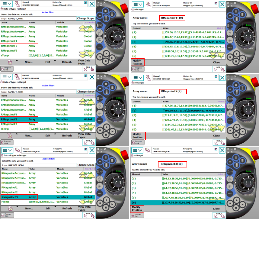
7. Teaching Mold Pickup and Drop-off Points
In the system, mold pickup and drop-off operations are performed on the same coordinate plane. For this reason, the definition made for the pickup point will automatically apply to the drop-off operation as well.
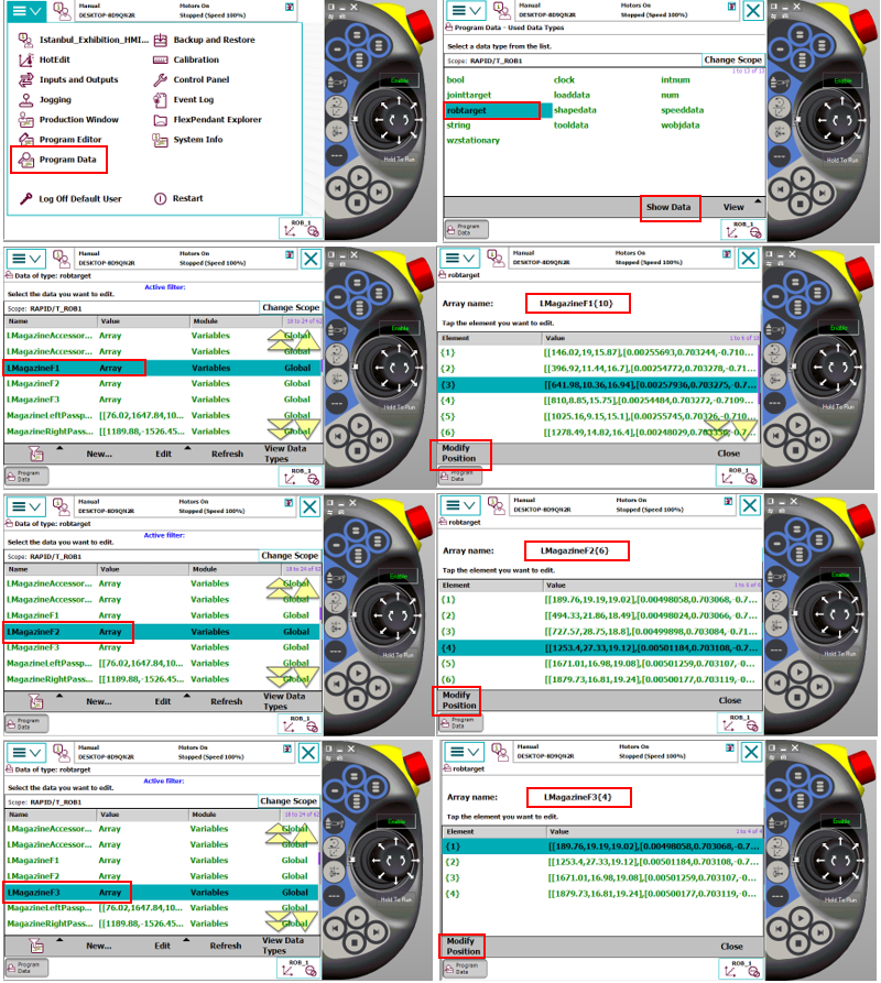
- Magazine Layout and Software Structure:
In the current system, there are Left and Right Magazine layouts, each consisting of 3 floors. These layouts are categorized as F1, F2, and F3 within the system, and the cell layout of each floor is defined with Array structures in software. This array structure allows the robot to navigate automatically and precisely to the sub-compartments within each floor.
IMPORTANT NOTE: All point definition and update operations must be performed while preserving the orientation values in the robot's standard work cycle. Point updating should not be done with randomly selected joint angles or orientations; it must be verified that the robot is at the correct approach angle to the target point. Records made at random positions can cause trajectory errors and mechanical collisions in automatic mode.
- The following steps must be followed when teaching the mold pickup point:
Alignment: The robot must be precisely positioned at the relevant pickup point in manual mode.
Mechanical Check: While the gripper is in the open position, it must be verified that the centering pins are exactly aligned with the recesses on the mold.
Lock Test: The gripper should be closed to check mechanical fit and holding security.
Recording: After verifying that the physical placement is error-free, the recording process of the reference point for the relevant Array element must be completed by following the visual instructions specified below.
NOTE: The robot must be in Manual Mode for this operation.
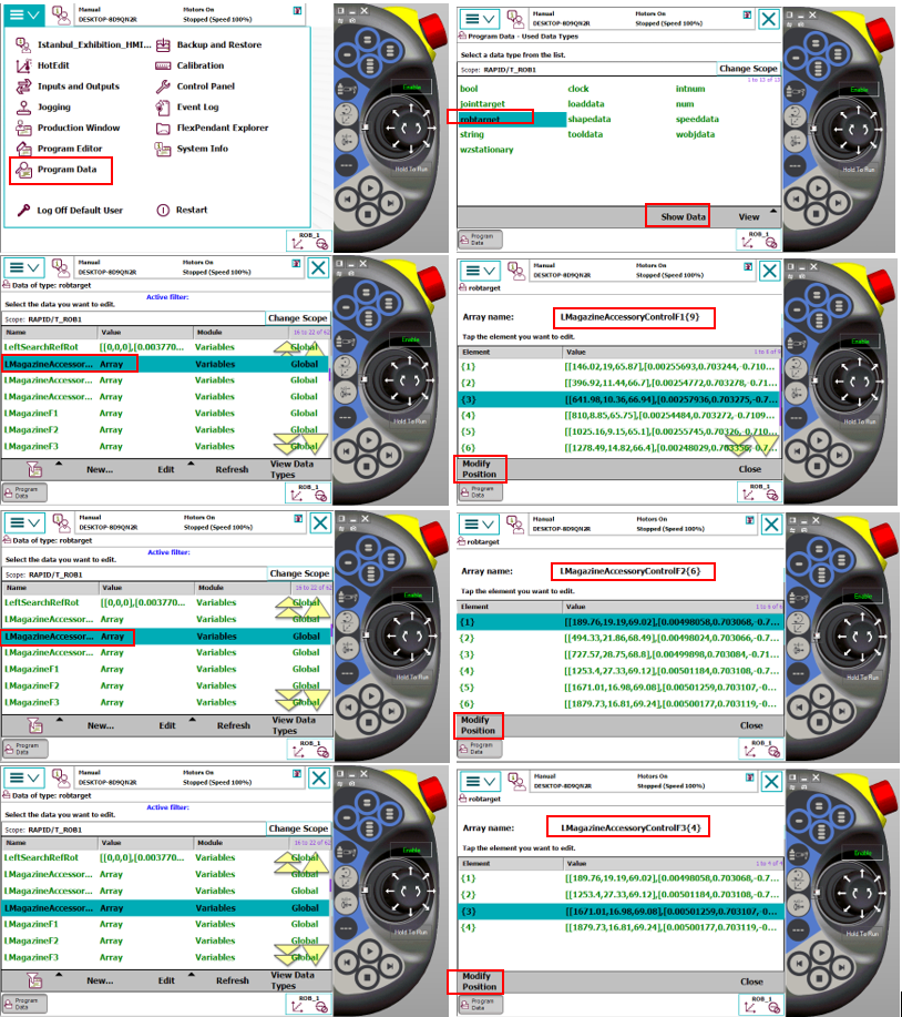
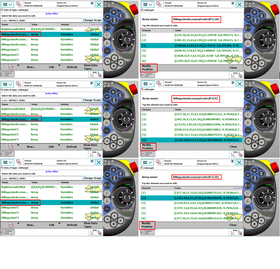
8. Teaching Accessory Control Points
Each accessory in the system has its own control sensor for presence/absence verification. The following procedure must be followed to correctly define the accessory control point:
- Alignment and Positioning:
After the robot takes the mold from the relevant station, it should exit without compromising the grip plane and orientation (in a linear trajectory). The accessory should be positioned directly opposite the sensor and within the detection distance. The robot's position at this control point should be determined as the position where the sensor sees the accessory most stably and should be recorded.
- Software Structure:
As with pickup and drop-off points, accessory control points are also defined within Array structures specifically named for each accessory group. This allows separate and independent control coordinates to be created for each accessory type.
- Recording Operation: After precise positioning is completed, the point recording steps should be performed by following the visual instructions below.
NOTE: The robot must be in Manual Mode for this operation.
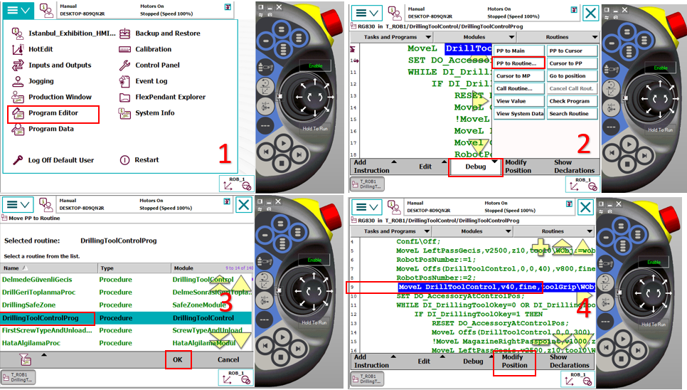
9. Teaching Drilling Tool Tip Control Point
Before the robot starts a drilling operation, it checks the integrity of the drill bit (break detection) through the DrillingToolControlProg routine. For the system to perform this check properly, correct teaching of the reference control point is critical.
- Points to Pay Attention:
Just like in pickup and drop-off operations, the control point must be taught in the same orientation suitable for the robot's own operation cycle. The robot approaching this point with standard work angle increases detection precision and prevents trajectory errors.
The definition and recording steps of this point are detailed in the images below